
 Kia Sorento: Schematic Diagrams
Circuit Diagram - ESC (1)
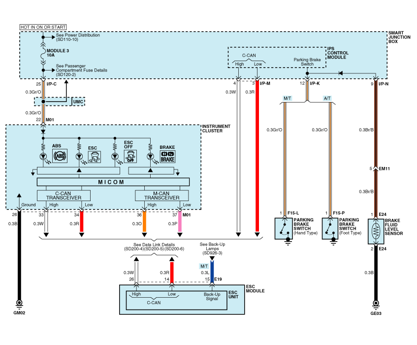
Circuit Diagram - ESC (2)
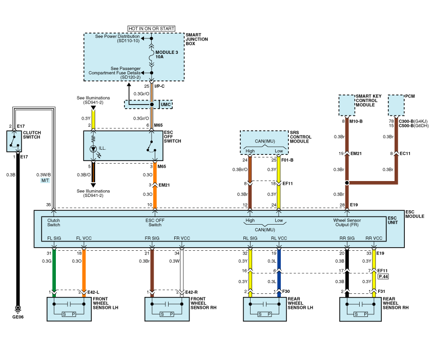
Circuit Diagram - ESC (3)
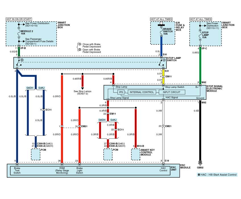
Circuit Diagram - ESC (4)
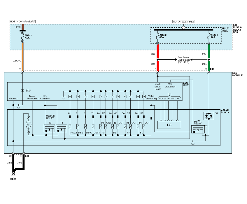
ESC connector input/output
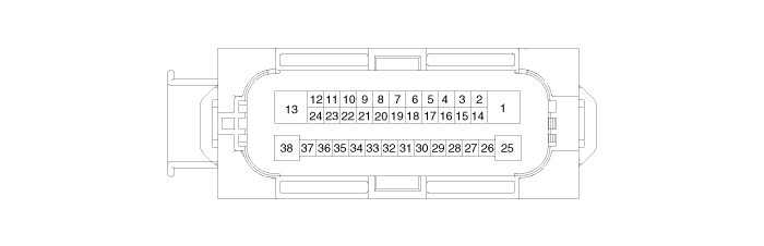
| Connector Terminal |
Specification |
|
| Pin No |
Description |
|
| 29 |
IGNITION1(+) |
High level of wake up voltage : 4.5V < V < 16.0V Low level of wake up voltage : V < 2.4V Max. current : I < 50mA |
| 25 |
POS. BATTERY 1.(SOLENOID) |
Over voltage range : 17.0 |
 ESC Operation Mode
 Failure Diagnosis
See also:
Troubleshooting
Symptom
Suspect Area
Remedy (Refer to page)
Water leaks from panorama sunroof
Deteriorated roof lid weatherstrip
Replace
Excessive roof lid ...
High Mounted stop lamp Removal
High Mounted Stop Lamp
1.
Disconnect the negative (-) battery terminal.
2.
Remove the tailgate trim.
(Refer to Body - " ...
Cylinder Block Reassembly
1.
Install the oil jet (A).
Tightening torque :
24.5 ~ 29.4 N.m (2.5 ~ 3.0 kgf.m, 18.1 ~ 21.7 lb-ft)
...
Manuals list
- Kia Sorento MQ4 2021-2026 Owners Manual
- Kia Sorento XM 2011-2015 Owners Manual
- Kia Sorento XM 2011-2015 Service Manual
