
 Kia Sorento: OBD-II review
1. Overview
The California Air Resources Board (CARB) began regulation of On Board
Diagnostics (OBD) for vehicles sold in California beginning with the 1988 model
year. The first phase, OBD-I, required monitoring of the fuel metering system,
Exhaust Gas Recirculation (EGR) system and additional emission related components.
The Malfunction Indicator Lamp (MIL) was required to light and alert the driver
of the fault and the need for repair of the emission control system. Associated
with the MIL was a fault code or Diagnostic Trouble Code (DTC) idenfying the
specific area of the fault.
The OBD system was proposed by CARB to improve air quality by identifying
vehicle exceeding emission standards. Passage of the Federal Clean Air Act Amendments
in 1990 has also prompted the Environmental Protection Agency (EPA) to develop
On Board Diagnostic requirements. CARB OBD-II regulations were followed until
1999 when the federal regulations were used.
The OBD-II system meets government regulations by monitoring the emission
control system. When a system or component exceeds emission threshold or a component
operates outside tolerance, a DTC will be stored and the MIL illuminated.
The diagnostic executive is a computer program in the Engine Control Module
(ECM) or PowertrainControl Module (PCM) that coordinates the OBD-II self-monitoring
system. This program controls all the monitors and interactions, DTC and MIL
operation, freeze frame data and scan tool interface.
Freeze frame data describes stored engine conditions, such as state of
the engine, state of fuel control, spark, RPM, load and warm status at the point
the first fault is detected. Previously stored conditions will be replaced only
if a fuel or misfire fault is detected. This data is accessible with the scan
tool to assist in repairing the vehicle.
The center of the OBD-II system is a microprocessor called the Engine
Control Module (ECM) or Powertrain Control Module(PCM).
The ECM or PCM receives input from sensors and other electronic components
(switches, relays, and others) based on information received and programmed
into its memory (keep alive random access memory, and others), the ECM or PCM
generates output signals to control various relays, solenoids and actuators.
2. Configuration of hardware and related terms
1) GST (Generic scan tool)
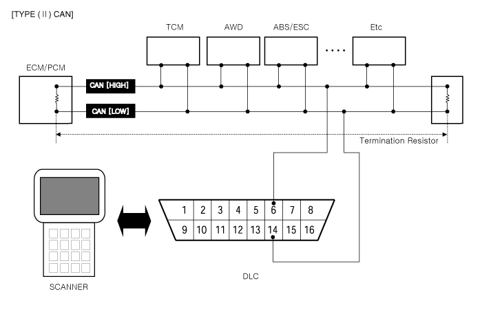
2) MIL (Malfunction indication lamp) - MIL activity by transistor
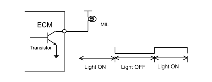
The Malfunction Indicator Lamp (MIL) is connected between ECM or PCM-terminal
Malfunction Indicator Lamp and battery supply (open collector amplifier).
In most cars, the MIL will be installed in the instrument panel. The lamp
amplifier can not be damaged by a short circuit.
Lamps with a power dissipation much greater than total dissipation of
the MIL and lamp in the tester may cause a fault indication.
▷ At ignition ON and engine revolution (RPM)< MIN. RPM, the MIL is switched
ON for an optical check by the driver.
3) MIL illumination
When the ECM or PCM detects a malfunction related emission during the
first driving cycle, the DTC and engine data are stored in the freeze frame
memory. The MIL is illuminated only when the ECM or PCM detects the same malfunction
related to the DTC in two consecutive driving cycles.
4) MIL elimination
 Engine Control System
1. Engine Control Module (ECM)
2. Manifold Absolute Pressure Sensor (MAPS)
3. Intake Air Temperature Sensor (IATS)
4. Engine Coolant Temperature Sensor (ECTS)
5. Throttle Position Sensor (...
 Components Location
See also:
Window opening and closing
Opening and closing cabin windows on the Kia Sorento is controlled directly using the individual power window
switches on each door panel.
Type A - Standard manual control switch
...
4WD ECU Input&Output Diagram
...
Immobilizer Control Unit Removal
1.
Disconnect the negative (-) battery terminal.
2.
Remove the crash pad lower panel (A).
(Refer to Body - "Crash pad")
...
Manuals list
- Kia Sorento MQ4 2021-2026 Owners Manual
- Kia Sorento XM 2011-2015 Owners Manual
- Kia Sorento XM 2011-2015 Service Manual

Copyright © xm.ksmanual.com 2014-2026 - 0.0305