
 Kia Sorento: Timing Chain Installation
Kia Sorento (XM, 2011-2015) Service Manual / Engine Mechanical System / Timing System / Timing Chain Installation
| 1. |
Install the balance shaft chain.
(Refer to Lubrication system - "Balance Shaft & Oil Pump")
|
| 2. |
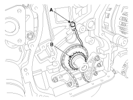
Install the crankshaft chain sprocket (B) and the timing chain oil jet
(A).
|
| 3. |
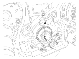
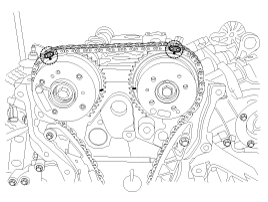
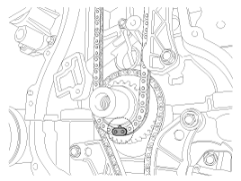
Set the crankshaft so that the key (A) of crankshaft will be aligned
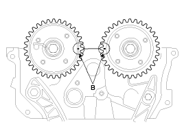
with the mating surface of main bearing cap. Put the intake and exhaust
camshaft assembly so that the TDC marks (B) of the intake and exhaust
CVVT sprockets will be aligned with the top surface of cylinder head.
As a result of this, the piston of No.1 cylinder is placed at the top
dead center on compression stroke.
|
| 4. |
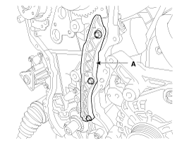
Install the timing chain guide (A).
|
| 5. |
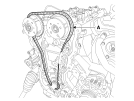
Install the timing chain. To install the timing chain with no slack
between each shaft (cam, crank), follow the below procedure.
Crankshaft sprocket (A) → Timing chain guide (B) → Intake CVVT sprocket
(C) → Exhaust CVVT sprocket (D).
|

| 6. |
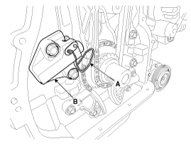
Install the timing chain tensioner arm (A).
|
| 7. |
Install the timing chain auto tensioner (B) and remove the stopper pin
(A).
|
| 8. |
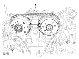
After rotating crankshaft 2 revolutions in regular direction (clockwise
viewed from front), confirm that the TDC marks (A) on the intake and
exhaust CVVT sprockets aligned with the top surface of cylinder head.
|
| 9. |
Install the timing chain cover.
(Refer to Timing System - "Timing Chain Cover")
|
| 10. |
Install cylinder head cover.
(Refer to Cylinder Head Assembly - "Cylinder Head Cover")
|
| 11. |
Add all the necessary fluids and check for leaks. Connect GDS. Check
for codes, note, and clear. Recheck.
|
 Timing Chain Inspection
 Cylinder Head Assembly
