 Kia Sorento: Balance Shaft & Oil Pump Installation
BSM(Balance Shaft Module) Chain System
|
1. |
The key of crankshaft should be aligned with the mating face of main
bearing cap. As a result of this, the piston of No.1 cylinder is placed
at the top dead center on compression stroke.
|
|
2. |
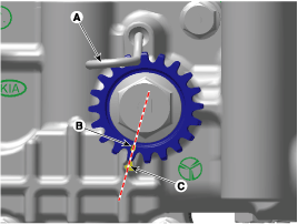
Insert a stopper pin (A) on the BSM to hold the sprocket at the reference
position with the timing mark (B) aligned with the timing notch (C).
|
New BSM has already been installed with a stopper pin at the
reference position.
|
|
|
3. |
Install the BSM (Balance Shaft Module).
|
(1) |
Tighten the bolts with seating torque 29.4 N.m (3.0kgf.m, 21.7
lb-ft) and then loosen the bolts.
|
|
(2) |
Using the SST (Torque Angle Adapter, 09221-4A000), tighten the
bolts with specified tightening torgue and angle.
Tightening torque
Bolts (A) (M9x181.5) : 22.6 ~ 26.5 N.m (2.3 ~ 2.7 kgf.m,
16.6 ~ 19.5 lb-ft) + 88° ~ 92°
Bolts (B) (M9x100) : 22.6 ~ 26.5 N.m (2.3 ~ 2.7 kgf.m,
16.6 ~ 19.5 lb-ft) + 43° ~ 47°
|
|
Do not reuse the BSM bolts.
|
|
|
|
4. |
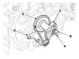
Install the balance shaft chain (E).
|
The timing marks of BSM sprocket and crankshaft sprocket should
be matched with the timing marks (color link) of balance shaft
chain.
|
|
|
5. |
Install the balance shaft chain guide (D).
Tightening torque :
9.8 ~ 11.8 N.m (1.0 ~ 1.2 kgf.m, 7.2 ~ 8.7 lb-ft)
|
|
|
6. |
Install the balance shaft chain tensioner arm (C).
Tightening torque :
9.8 ~ 11.8 N.m (1.0 ~ 1.2 kgf.m, 7.2 ~ 8.7 lb-ft)
|
|
|
7. |
Install the balance shaft chain tensioner (B) then remove the stopper
pin (A).
Tightening torque :
9.8 ~ 11.8 N.m (1.0 ~ 1.2 kgf.m, 7.2 ~ 8.7 lb-ft)
|
|
|
8. |
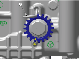
Remove the stopper pin (A) of balance shaft module.
|
|
9. |
After rotating crankshaft 2 revolutions in regular direction (clockwise
viewed from front), confirm that the timing mark and notch are aligned
at the reference position.
|
|
10. |
Install the other parts in the reverse order of removal.
|
BSM (Balance Shaft Module)
|
1. |
Insert a stopper pin (A) on the BSM to hold the sprocket at the reference
position with the timing mark (B) aligned with the timing notch (C).
|
New BSM has already been installed with a stopper pin at the
reference position.
|
|
|
2. |
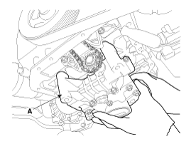
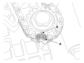
Install the BSM (Balance Shaft Module) (A).
|
The timing mark of BSM sprocket should be matched with the paint-marked
link of the timing chain.
|
|
|
3. |
Install the BSM mounting bolts.
|
(1) |
Tighten the bolts with seating torque 29.4 N.m (3.0kgf.m, 21.7
lb-ft) and then loosen the bolts.
|
|
(2) |
Using the SST (Torque Angle Adapter, 09221-4A000), tighten the
bolts with specified tightening torgue and angle.
Tightening torque
Bolts (A) (M9x181.5) : 22.6 ~ 26.5 N.m (2.3 ~ 2.7 kgf.m,
16.6 ~ 19.5 lb-ft) + 88° ~ 92°
Bolts (B) (M9x100) : 22.6 ~ 26.5 N.m (2.3 ~ 2.7 kgf.m,
16.6 ~ 19.5 lb-ft) + 43° ~ 47°
|
|
Do not reuse the BSM bolts.
|


|
|
|
4. |
Remove the stopper pin (A) from the BSM.
|
|
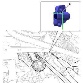
5. |
Remove the stopper pin (A) from the tensioner.
|
|
6. |
Confirm the BSM timing mark.
|
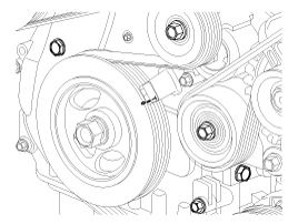
(1) |
Turn the crankshaft pulley and align its groove with the timing
mark "T" of the timing chain cover.
|
|
(2) |
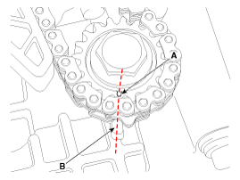
Confirm that the sprocket timing mark (A) is visually aligned
with center of adjacent cast timing notch (B).
|
|
|
7. |
Install the oil pan.
|
(1) |
Using a gasket scraper, remove all the old sealant material
from the gasket surfaces.
|
|
(2) |
Before assembling the oil pan, liquid sealant Loctite 5900H,
Threebond 1217H or equivalent should be applied on oil pan.
The part must be assembled within 5 minutes after sealant was
applied.
Bead width : 2.5 mm
(0.10 in.)
|
|
• |
When applying sealant gasket, sealant must not
be protruded into the inside of oil pan.
|
|
• |
To prevent leakage of oil, apply sealant gasket
on the inner threads of the bolt holes.
|
|
|
|
(3) |
Install the oil pan (A). Uniformly tighten the bolts in several
passes.
Tightening torque
Bolts B (M9) : 26.5 ~ 30.4 N.m (2.7 ~ 3.1 kgf.m, 19.5
~ 22.4 lb-ft)
Bolts C (M6) : 9.8 ~ 11.8 N.m (1.0 ~ 1.2 kgf.m, 7.2
~ 8.7 lb-ft)
|

|
• |
After assembly, wait at least 30 minutes before
filling the engine with oil.
|
|
• |
Always use a new drain plug gasket.
|
|
|
|
|
8. |
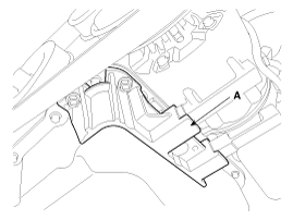
Install the A/C compressor bracket (A).
Tightening torque :
19.6 ~ 23.5 N.m (2.0 ~ 2.4 kgf.m, 14.5 ~ 17.4 lb-ft)
|
|
|
9. |
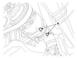
Remove the A/C compressor lower mounting bolts (A).
Tightening torque :
19.6 ~ 24.5 N.m (2.0 ~ 2.5 kgf.m , 14.5 ~ 18.1 Ib-ft)
|
|
|
10. |
Refill with engine oil.
|
|
11. |
Install the RH front wheel.
|
|
12. |
Install the under cover.
|
BSM (Balance Shaft Module) Chain System
1.
Remove the timing chain.
(Refer to Timing System in this group)
2.
Install a stopper pin (A)...
1.
Check the continuity between the terminal and the body with an ohmmeter.
If there is no continuity, replace the oil pressure switch.
2.
...



 Balance Shaft & Oil Pump Removal
 Oil Pressure Switch Inspection
