
Kia Sorento: Front Driveshaft Removal and Installation - Driveshaft Assembly - Driveshaft and axleKia Sorento: Front Driveshaft Removal and Installation

Kia Sorento (XM, 2011-2015) Service Manual / Driveshaft and axle / Driveshaft Assembly / Front Driveshaft Removal and Installation

1.
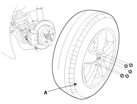
Remove the front wheel and tire (A) from front hub .

Tightening torque:
88.2 ~ 107.8 N.m (9.0 ~ 11.0 kgf.m, 65.0 ~ 79.5 lb-ft)

  
Be careful not to damage to the hub bolts when removing the front wheel and tire (A).

2.
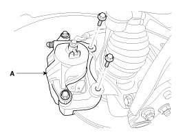
Remove the brake caliper mounting bolts, and then place the brake caliper assembly (B) with wire.

Tightening torque:
78.4 ~ 98.0N.m (8.0 ~ 10.0kgf.m, 57.8 ~ 72.3lb-ft)

3.
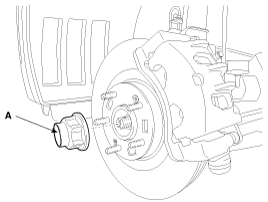
Remove the coking nut (A).

Tightening torque:
240.3~ 269.7N.m (24.5 ~ 27.5kgf.m, 177.2 ~ 198.9lb-ft)

  
The front hub coking nut should be replaced with new ones.
After installation coking nut (A), stake the coking nut using a chisel and hammer as shown in the illustration below.

4.
Remove the brake hose (A) and wheel speed sensor (B).

Tightening torque:
6.8 ~ 10.8N.m (0.7 ~ 1.1kgf.m, 5.1 ~ 7.9lb-ft)

5.
Remove the tie rod end ball joint (C) from the knuckle.
(1)
Remove the split pin (A).
(2)
Remove the castle nut (B).

Tightening torque:
34.3 ~ 44.1N.m (3.5 ~ 4.5kgf.m, 25.3 ~ 32.5lb-ft)

6.
Disconnect the ball joint(A) from knuckle using the special tool (09568-4A000).

7.
Remove the lower arm (A) mounting bolt and nut from the knuckle.

Tightening torque:
98.0 ~ 117.6N.m (10.0 ~ 12.0kgf.m, 72.3 ~ 86.7lb-ft)

8.
Using a plastic hammer (A), disconnect driveshaft (C) from the axle hub (B).

9.
Remove the RH side cover (A).

Tightening torque:
7.8 ~ 11.8N.m (0.8 ~ 1.2kgf.m, 5.8 ~ 8.7lb-ft)

10.
Remove the mounting bolts (A,B) of Upper roll rod bracket (C).

Tightening torque:
(A) 107.9 ~ 125.5N.m (11.0 ~ 13.0kgf.m, 79.6 ~ 94.0lb-ft)
(B) 49.0 ~ 63.7N.m (5.0 ~ 6.5kgf.m, 36.2 ~ 47.0lb-ft)

  
Do not reuse bolts.

11.
Loosen the inner shaft mounting bolts and then disconnect the inner shaft (A).

Tightening torque:
49.0 ~ 68.6N.m (5.0 ~ 7.0kgf.m, 36.2 ~ 50.6lb-ft)

  
By the shape and the engine bracket bolts are mounted differently.

12.
Insert a pry bar (A) between the transaxle case and joint case, and separate the drive shaft (B) from the transaxle case.

13.
Install in the reverse order of removal.
  
Use a pry bar being careful not to damage the transaxle and joint.
Do not insert the pry bar too deep, as this may cause damage to the oil seal.
Do not pull the driveshaft by excessive force it may cause components inside the joint kit to dislodge resulting in a torn boot or a damaged bearing.
Plug the hole of the transaxle case with the oil seal cap to prevent contamination.
Support the driveshaft properly.
Replace the retainer ring whenever the driveshaft is removed from the transaxle case.
Front Driveshaft Components
1. Front driveshaft (LH) 2. Inner shaft bearing bracket 3. Front driveshaft (RH) [LH] 1. BJ assembly 2. Clip 3. BJ boot band 4. BJ boot 5. Dy...
TJ Joint Components
[LH] 1. BJ assembly 2. BJ circlip 3. BJ boot band 4. BJ boot 5. Shaft 6. TJ boot band 7. TJ boot 8. Spider assembly 9. Retainer ring 10. TJ hous...
See also:

Basic function
Basic functions designed to empower the Forward Collision-Avoidance Assist architecture on your Kia Sorento include: Collision Warning Emergency Braking ...

IMS Power Seat Control Installation
1. Install the power seat control switch after connecting the connector. ...

Using the Tire Mobility Kit
CAUTION Detach the speed restriction label from the sealant bottle, and place it in a highly visible place inside your Kia Sorento, such as on the steering wheel, to remind the driver not t ...

Copyright © xm.ksmanual.com 2014-2026