
Kia Sorento: Rear Driveshaft Removal and Installation - Rear Driveshaft Assembly - Driveshaft and axleKia Sorento: Rear Driveshaft Removal and Installation

Kia Sorento (XM, 2011-2015) Service Manual / Driveshaft and axle / Rear Driveshaft Assembly / Rear Driveshaft Removal and Installation

1.
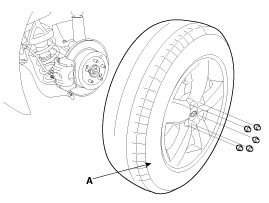
Remove the rear wheel and tire (A) from rear hub.

Tightening torque:
88.2 ~ 107.8 N.m (9.0 ~ 11.0 kgf.m, 65.0 ~ 79.5 lb-ft)

  
Be careful not to damage to the hub bolts when removing the front wheel and tire (A).
2.
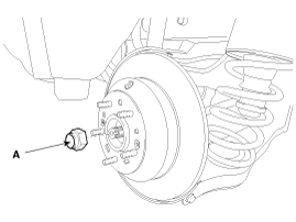
Remove the coking nut (A).

Tightening torque:
240.3~ 269.7N.m (24.5 ~ 27.5kgf.m, 177.2 ~ 198.9lb-ft)

3.
Remove the rear shock absorber.
(Refer to Suspension System - "Rear Shock Absorber")
4.
Remove the parking brake cable.
(Refer to Brake System - "Parking Brake Cable")
5.
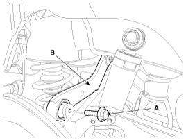
Remove the rear upper arm (A) after loosen the bolt (B).

Tightening torque
98.0 ~ 117.6N.m (10.0 ~ 12.0kgf.m, 72.3 ~ 86.7lb-ft)

6.
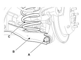
Remove the rear lower arm (B), spring (C) as loosening bolt (A) after supporting rear lower arm (B) with jack.

Tightening torque:
137.2 ~ 156.9N.m (14.0 ~ 16.0kgf.m, 101.2 ~ 115.7lb-ft)

  
Certainly install Jack as being danger because of the tension.

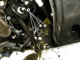
7.
Remove the rear assist arm (C), trailing arm (D) as loosening bolt (A), nut (B).

Tightening torque:
(A) : 44.1 ~ 53.9N.m (4.5 ~ 5.5kgf.m, 32.5 ~ 39.8lb-ft)
(B) : 137.3 ~ 156.9N.m (14.0 ~ 16.0kgf.m, 101.3 ~ 115.7lb-ft)

8.
Separate the end (B) of rear driveshaft on rear axle assembly (A).
  
To prevent damage to the drive shaft.
Check for damage after the completion of work.
Remove the drive shaft is not possible to prevent damage to the work.

9.
Insert a pry bar (A) between the differential case (B) and joint case (C), and separate the driveshaft (D) from the differential case.
  
Use a pry bar being careful not to damage the transaxle and joint.
Do not insert the pry bar too deep, as this may cause damage to the oil seal.
Do not pull the driveshaft by excessive force it may cause components inside the joint kit to dislodge resulting in a torn boot or a damaged bearing.
Plug the hole of the transaxle case with the oil seal cap to prevent contamination.
Support the driveshaft properly.
Replace the retainer ring whenever the driveshaft is removed from the transaxle case.

10.
Install in the reverse order of removal.
11.
Check the wheel alignment.
(Refer to Suspension System - "Alignment")
Rear Driveshaft Components
1. Tone wheel 2. BJ joint 3. BJ boot 4. BJ boot big part band 5. BJ boot small part band 6. Shaft 7. TJ boot small part band 8. TJ boot big part band 9. TJ boot 10. Snap...
Rear Driveshaft Inspection
1. Check the driveshaft boots for damage and deterioration. 2. Check the ball joint for wear and damage. 3. Check the spli...
See also:

Component Location
1. Cluster assembly 2. Seat belt switch 3. Vehicle speed sensor 4. Engine coolant temperature sender 5. Oil pressure switch 6. Brake fluid level warning switch 7. Parking ...

Tire Removal
1. Remove valve core and deflate the tire. 2. Remove the side of the tire bead area from the wheel using tire changing machine . ...

Panoramic sunroof (if equipped)
If your vehicle comes fitted with the panoramic glass sunroof, you can conveniently open, close, or tilt the glass panel using the integrated overhead console sunroof switch. ...

Copyright © xm.ksmanual.com 2014-2026