
 Kia Sorento: Relay Box (Engine Compartment) Inspection
| 1. |
Disconnect the negative (-) battery terminal.
|
| 2. |
Pull out the relay from the engine compartment relay box.
|
| 1. |
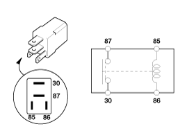
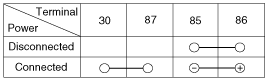
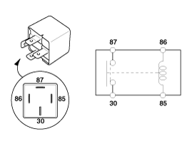
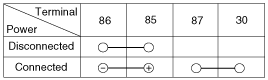
There should be continuity between the No.30 and No.87 terminals
when power and ground are connected to the No.85 and No.86 terminals.
|
| 2. |
There should be no continuity between the No.30 and No.87 terminals
when power is disconnected.
|
| 1. |
There should be continuity between the No.30 and No.87 terminals
when power and ground are connected to the No.85 and No.86 terminals.
|
| 2. |
There should be continuity between the No.30 and No.87a terminals
when power is disconnected.
|
| 3. |
There should be no continuity between the No.30 and No.87 termianls
when power is disconnected.
|
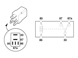
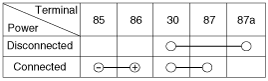
| 1. |
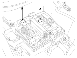
There should be continuity between the No.30 and No.87 terminals
when power and ground are connected to the No.85 and No.86 terminals.
|
| 2. |
There should be no continuity between the No.30 and No.87 terminals
when power is disconnected.
|
| 1. |
Be sure there is no play in the fuse holders, and that the fuses
are held securely.
|
| 2. |
Are the fuse capacities for each circuit correct?
|
| 3. |
Are there any blown fuses?
If a fuse is to be replaced, be sure to use a new fuse of the
same capacity. Always determine why the fuse blew first and completely
eliminate the problem before installing a new fuse.
|
|

| 1. |
Disconnect the negative(-) battery terminal.
|
| 2. |
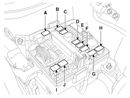
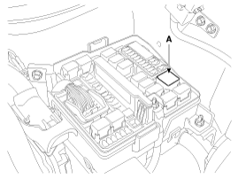
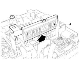
Push 3 hooks in the engine room relay box out to the arrow direction
and put up the EMS box assembly (A).
|
| 3. |
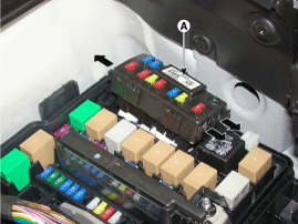
Disconnect the connector and remove the EMS box assembly (A).
|
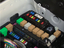
 Relay Box (Engine Compartment) Component Location
 Relay Box (Passenger Compartment) Component Location
See also:
Master Cylinder Components and Components Location
Components
1. Reservoir cap2. Reservoir3. Master
cylinder
4. Brake booster5. Push rod6. Vacuum sensor
...
Fuel Sender Specifications. Fuel Sender Components and Components Location
Fuel Sender Specifications
Specification
Position
Resistance (Ω)
Capacity [ℓ (U.S.gal., U.S.qt., Imp.q ...
CVVT & Camshaft Operation Principle
The CVVT has the mechanism rotating the rotor vane with hydraulic force generated
by the engine oil supplied to the advance or retard chamber in accordance with
the CVVT oil control valve con ...
Manuals list
- Kia Sorento MQ4 2021-2026 Owners Manual
- Kia Sorento XM 2011-2015 Owners Manual
- Kia Sorento XM 2011-2015 Service Manual
