
 Kia Sorento: Schematic Diagram
Kia Sorento (XM, 2011-2015) Service Manual / Emission Control System / Evaporative Emission Control System / Schematic Diagram
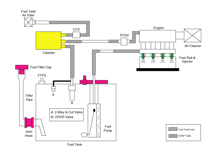
Canister
Canister is filled with charcoal and absorbs evaporated vapor in fuel
tank. The gathered fuel vapor in canister is drawn into the intake manifold
by the ECM/PCM when appropriate conditions are set.
Purge Control Solenoid Valve (PCSV)
Purge Control Solenoid Valve (PCSV) is installed in the passage connecting
canister and intake manifold. It is a duty type solenoid valve and is operated
by ECM/PCM signal.
To draw the absorbed vapor into the intake manifold, the ECM/PCM will
open the PCSV, otherwise the passage remains closed.
Fuel Filler Cap
A ratchet tightening device on the threaded fuel filler cap reduces the
chances of incorrect installation, seals the fuel filler. After the gasket on
the fuel filler cap and the fill neck flange make contact, the ratchet produces
a loud clicking noise indicating the seal has been set.
Fuel Tank Pressure Sensor (FTPS)
The Fuel Tank Pressure Sensor (FTPS) is an integral part of the monitoring
system. The FTPS checks Purge Control Solenoid Valve (PCSV) operation and leaks
in the Evaporative Emission Control System by monitoring pressure and vacuum
level in the fuel tank during PCSV operating cycles.
Canister Close Valve (CCV)
The Canister Close Valve (CCV) is located between the canister and the
fuel tank air filter. It closes off the air inlet to the canister for the Evaporative
Emissions System and also prevents fuel vapors from escaping from the Canister
when the vehicle is not operating.
Evaporative System Monitoring
Evaporative Emission Control Monitoring System consists of fuel vapor
generation, evacuation, and leakage check step. At first, the OBD-II system
checks if vapor generation due to fuel temperature is small enough to start
monitoring. Then it evacuates the evaporative system by means of PCSV with ramp
in order to maintain a certain vacuum level. The final step is to check if there
is vacuum loss by any leakage of the system.
Vapor Generation Checking
During stabilization period, the PCSV and the CCV are closed. The system
pressure is measured as starting pressure (DP_A). After a certain defined period
(T1), the system pressure (DP_B) is measured again and the difference from the
starting pressure is calculated. If this difference (DP_B - DP_A) is bigger
than a threshold, there should be excessive vapor and the monitor is aborted
for next checking. On the contrary, if the difference is lower than another
negative threshold, PCSV is regarded as malfunction such as clogged at open
position.
Evacuation
PCSV is opened with a certain ramp for the pressure to reach down to a
certain level. If pressure can
Evaporative System Monitoring
Evaporative And ORVR Emission Control System
This system consists of below items;
-
Fill vent valve
-
Fuel...
 Operation
1. Purge Control Solenoid Valve (PCSV)
2. Vapor line
3. Fuel tank air filter
4. Canister Close Valve (CCV)
5. Canister
6. Fuel Tank Pressure Sensor (FTPS)...
 Components Location
See also:
Illuminated ignition switch (if equipped)
Whenever a front door is opened, the ignition switch will illuminate for your
convenience, provided the ignition switch is not in the ON position. The light will
go off immediately when the igniti ...
Front Door Components
1. Door grip handle cover
2. Door inside handle cap
3. Door trim
4. Door belt inner weatherstrip
5. Door module
6. Quadrant inner cover
7. Door belt weatherstrip
8. ...
Photo Sensor Description
The photo sensor is located at the center of the defrost nozzles.
The photo sensor contains a photovoltaic (sensitive to sunlight) diode.
The solar radiation received by its light receiving ...
Manuals list
- Kia Sorento MQ4 2021-2026 Owners Manual
- Kia Sorento XM 2011-2015 Owners Manual
- Kia Sorento XM 2011-2015 Service Manual

Copyright © xm.ksmanual.com 2014-2026 - 0.0395