
 Kia Sorento: Parking Brake Lever Assembly Installation
Kia Sorento (XM, 2011-2015) Service Manual / Brake System / Parking Brake System / Parking Brake Lever Assembly Installation
| 1. |
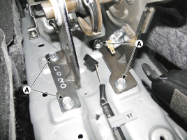
Install the parking brake lever assembly (A).
|
| 2. |
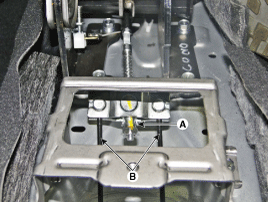
Install the parking brake cable (B) and tighten the adjusting
nut (A).
|
| 3. |
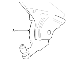
Apply a coating of the specified grease to each sliding parts
(A) of the ratchet plate or the ratchet pawl.
|
| 4. |
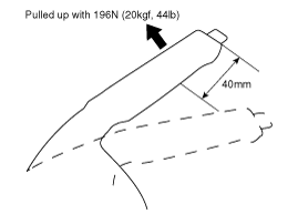
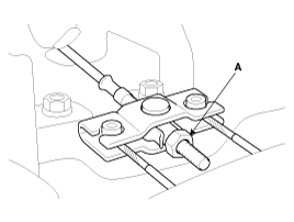
Install the parking brake cable adjuster, then adjust the parking
brake lever stroke by turning adjusting nut (A).
|

| 5. |
Release the parking brake lever fully, and check that parking
brakes do not drag when the rear wheels are turned. Readjust if necessary.
|
| 6. |
Make sure that the parking brakes are fully applied when the parking
brake lever is pulled up fully.
|
| 7. |
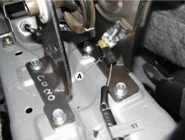
Reconnect the connector (A) of parking brake switch.
|
| 8. |
Install the floor console.
(Refer to Body - "Floor console")
|
The parking brake cables must not be bent or distorted. This will
lead to stiff operation and premature failure.
1.
...
 Parking Brake Lever Assembly Removal
Parking Brake Lever Stroke Adjustment
1.
Remove the floor console.
(Refer to Body - "Floor console")
2.
Apply the brake peda...
 Parking Brake Lever Assembly Adjustment
See also:
Auto Light Switch Inspection
Operate the auto light switch, then check for continuity between terminals
of multi-function switch connector.
...
Removal
Replacing an on/off solenoid valve (SS-A, SS-B) does not require
additional hydraulic pressure adjustment; however, the ...
Children always in the rear
Children under 13 years of age must always ride seated in the rear passenger rows and must be properly secured in an
appropriate restraint system to minimize the risk of severe injury during a co ...
Manuals list
- Kia Sorento MQ4 2021-2026 Owners Manual
- Kia Sorento XM 2011-2015 Owners Manual
- Kia Sorento XM 2011-2015 Service Manual

Copyright © xm.ksmanual.com 2014-2026 - 0.0373